Before Customizing Blades, What Key Information Should Be Provided to the Manufacturer to Avoid Rework?
Sep 10, 2026
When customizing custom blades, rework is a headache for both parties. Rework not only extends delivery time and increases costs but may also delay the customer's production schedule. Mingbai Mechanical Tool Technology Co., Ltd., based on years of customization experience, has found that over 90% of rework stems from incomplete or inaccurate information provided upfront. This article outlines six major categories of key information that must be provided to the manufacturer before customizing blades, helping you get it right the first time and avoid rework.
1. Detailed Information About the Material Being Cut
Material information is the fundamental basis for blade design. Simply stating "cutting stainless steel" is far from enough. You need to provide:
Material grade: Such as 304, 316, 430, 50W470 silicon steel, etc. Different grades have vastly different hardness, toughness, and work-hardening tendencies.
Material thickness and tolerance range: Thickness determines edge angle and gap settings; tolerance range affects blade wear resistance requirements.
Material condition: Hard, soft, annealed? Any coating or plating?
Material width: Determines blade outer diameter and shaft length.
Special characteristics: Does it contain fiberglass? Is it highly adhesive? Are there joints?
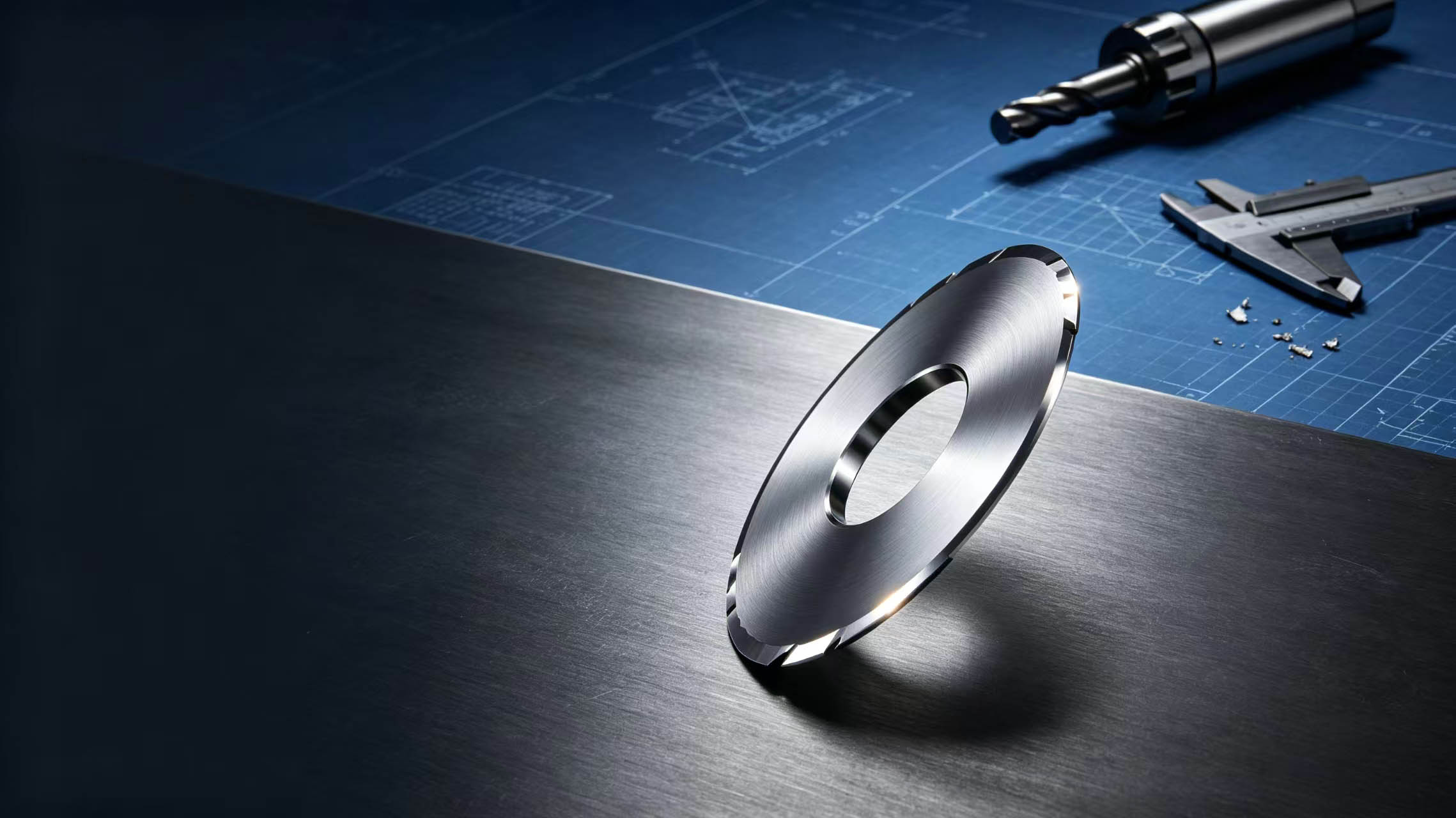
Circular blades for stainless steel strip slitting and alloy blades for silicon steel slitting have completely different edge designs and material selections due to different material characteristics.
2. Equipment Parameters and Working Conditions
Blades must match the equipment, otherwise even the highest precision cannot be used properly:
Equipment type and model: Slitting machine, slitter, rewinder? Brand and model?
Blade shaft diameter and keyway specifications: Determine blade bore size and keyway position.
Speed range: What is the line speed? High-speed conditions require higher dynamic balance grades.
Blade mounting method: Spacer positioning or hydraulic locking? Single blade or multi-blade combination?
Existing blade usage issues: Such as large burrs, short life, chipping, etc., to help the manufacturer optimize the design.
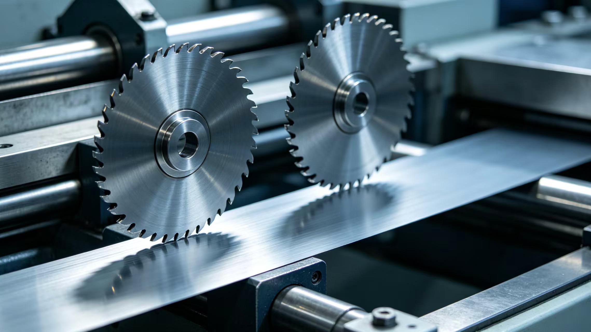
Blades for high-speed rotary slitting machines have high dynamic balance requirements, so accurate speed range must be provided.
3. Blade Dimensions and Geometric Parameters
Dimensional information must be precise to the drawing level, avoiding vague descriptions:
Outer diameter, bore, thickness: Specify exact values and tolerance ranges, e.g., outer diameter Φ200±0.02mm.
Edge angle: Specific values for wedge angle, rake angle, clearance angle, with tolerances.
Edge radius: Is micro-passivation required? What R value?
Keyway/mounting holes: Position, width, depth, angle; preferably provide 2D or 3D drawings.
Flatness, parallelism, concentricity: Higher precision requirements mean higher processing costs; must be clearly specified.
High-precision circular blades for precision strip slitting typically require concentricity ≤0.005mm, which must be clearly marked.
4. Precision Grade and Inspection Requirements
Precision requirements vary greatly for different working conditions:
Thickness tolerance: Standard grade ±0.01mm, precision grade ±0.005mm, ultra-precision grade ±0.002mm.
Parallelism: Standard grade 0.01mm, precision grade 0.005mm, ultra-precision grade 0.002mm.
Runout requirements: Specific values for radial runout and axial runout.
Inspection report: Is an outgoing inspection report required? Which inspection items?
Ultra-thin circular blades for lithium battery electrode slitting have extremely low burr tolerance, with precision requirements far exceeding ordinary slitting.
5. Surface Treatment and Coating Requirements
Coatings directly affect blade life and cutting quality:
Is coating required: TiN, TiCN, TiAlN, DLC?
Coating thickness requirements: Typically 2-4μm; too thick affects sharpness.
Surface roughness: Ra value requirements? Is mirror polishing required?
Rust prevention: Rust preventive oil, blackening treatment, or VCI packaging?
TiAlN coated carbide blades for high-speed stainless steel slitting — coating selection directly affects heat resistance and anti-adhesion performance.
6. Quantity, Delivery, and Packaging Requirements
Order quantity: Initial quantity and subsequent annual usage, to help the manufacturer schedule production.
Delivery cycle: Is the expected delivery date urgent?
Packaging method: Individual packaging or bulk packaging? Export wooden cases required?
Marking requirements: Is laser engraving of material, batch number, customer number required?
7. Mingbai Technology's Customization Information Checklist
To avoid rework, Mingbai Technology has prepared a custom blade information confirmation checklist for customers, covering the six major categories above. Customers simply fill in each item, and we can quickly evaluate and provide a solution. We also offer drawing review services, free of charge, to check whether the drawings provided by customers are complete and whether the parameters are reasonable.
Conclusion
Before customizing blades, the more complete the information provided, the lower the probability of rework. Material, equipment, dimensions, precision, coating, packaging — all six categories of information are indispensable. Mingbai Mechanical Tool Technology Co., Ltd. is ready to help you get it right the first time with a professional customization process, saving time and effort.
FAQ Module:
Q1: Can I provide only a sample instead of a drawing when customizing blades?
A: Yes, but note: old samples may be worn or deformed. During reverse engineering, the original dimensions must be deduced based on wear. It is also recommended to provide working condition information (material, equipment, speed) to help the manufacturer judge whether the original design is reasonable.
Q2: Why is it necessary to provide equipment speed?
A: Speed determines the blade's dynamic balance grade requirement. High-speed slitting (line speed >500m/min) must undergo dynamic balance verification; otherwise, vibration can cause blade chipping and equipment damage. Blades for high-speed rotary slitting machines especially require a clear speed range.
Q3: What edge angle should be specified?
A: It depends on the material being cut. Thin materials (<0.5mm) recommend 18°-22°, conventional materials 22°-25°, thick or high-hardness materials 25°-30°. If unsure, provide working conditions and let Mingbai engineers calculate the recommended value.
Q4: How to choose the precision grade?
A: For ordinary slitting, choose standard grade (thickness tolerance ±0.01mm); for precision slitting, choose precision grade (±0.005mm); for lithium battery electrodes, electronic foils, etc., choose ultra-precision grade (±0.002mm). Higher precision means higher cost; choose according to actual needs.
Q5: How long does it typically take to customize blades?
A: For conventional materials and specifications, delivery is 7-15 days after receiving confirmation information. For special materials (such as powder high-speed steel, carbide) or complex special-shaped blades, it takes 15-25 days. It is recommended to plan ahead and allow sufficient time.
https://www.mingbaiblade.com/

 Email: Mb@mingbaiblade.com
 Tel.: +86-13855519988


 IPv6 network supported |
Sitemap
|
Xml
|
Privacy Policy
IPv6 network supported |
Sitemap
|
Xml
|
Privacy Policy


 en
en