Small Cracks Appear on the Surface of Alloy Blades After Use — Can They Still Be Used?
Jul 03, 2026
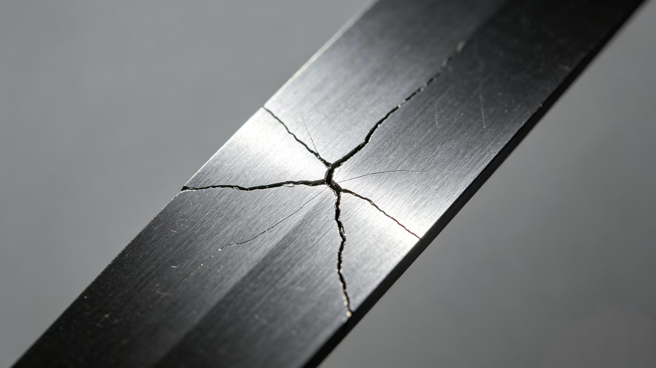
In slitting production, operators occasionally find small cracks on the surface of alloy blades. Some of these cracks are visible to the naked eye, while others can only be seen with a magnifying glass. When encountering such a situation, many people's first reaction is, "Can it still be used?" Mingbai Mechanical Tool Technology Co., Ltd., based on materials science and field experience, provides you with judgment criteria and handling recommendations.
1. Two Types of Cracks: Surface Cracks vs. Deep Cracks
Surface micro-cracks: The depth is usually less than 0.05mm, existing only in the blade's surface layer. Such cracks may be caused by grinding thermal stress, coating shrinkage stress, or minor impact. If the crack does not extend to the edge and the blade material is a tough high-speed steel blade, it may be temporarily usable under low-load conditions.
Deep cracks: Depth exceeds 0.1mm, or extends from the surface inward. Such cracks often originate from excessive heat treatment stress, quenching micro-cracks, or long-term fatigue. Once a deep crack appears, a carbide blade may fracture completely at any time and must be taken out of service immediately.
2. Common Causes of Cracks
1. Grinding burn
During resharpening, excessive feed rate or insufficient cooling causes localized overheating, producing grinding cracks. Such cracks are usually network-like or fine linear, distributed near the edge. Common in precision slitting circular blades.
2. Heat treatment defects
Quenching temperature too high or inadequate tempering leaves excessive residual stress inside the blade, which slowly releases during use and causes cracking.
3. Fatigue cracks
Alloy blades for silicon steel slitting are subjected to alternating cutting stress over long periods, and fatigue cracks initiate at stress concentration points.
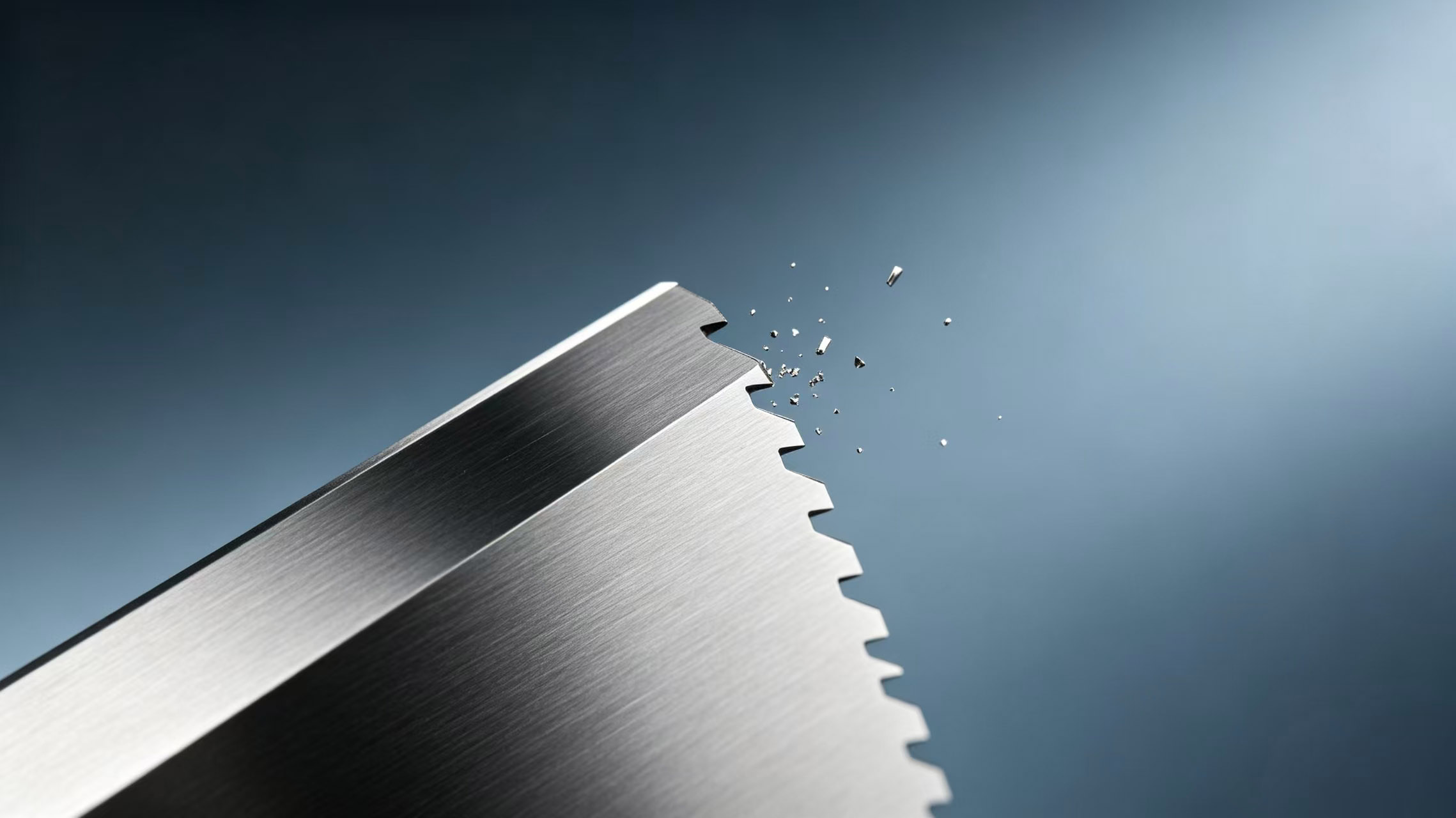
4. Impact cracks
The blade receives an unexpected impact (such as material joints or hard inclusions), causing localized chipping that extends into a crack.
5. Coating cracks
PVD coatings are hard but brittle. Under significant impact, the coating may crack while the substrate remains intact. Such cracks only affect coating life; the substrate of coated alloy blades can continue to be used.
3. Three-Step Method to Determine Whether It Can Still Be Used
Step 1: Identify the crack location
· Crack on the edge → Dangerous, pieces may fly off during cutting, must be taken out of service.
· Crack in a non-stressed area of the blade body, such as near the bore → Lower risk, can be used with short-term monitoring.
· Crack on the end face but not extending to the outer diameter → Further depth inspection needed.
Step 2: Assess crack depth
· Observe with a 10x or higher magnifying glass. If the crack is as fine as a hair and does not penetrate the surface → it may be a surface crack.
· Use dye penetrant inspection: clean the blade, apply penetrant, wipe off, then apply developer. If the developing line is continuous and clear → the crack is relatively deep.
· Gently scrape with a fingernail or a metal piece. If you can feel a noticeable groove → the depth may exceed 0.1mm.
Step 3: Decide based on working conditions
· Low speed, low load, non-safety-critical position → a surface crack may be temporarily usable, but increase inspection frequency.
· High speed, high load, automated production line → any crack is recommended to be taken out of service.
· Cutting valuable materials or involving personnel safety → replace immediately.
4. Crack Tolerance for Different Blade Materials
· High-speed steel blades: Good toughness, surface micro-cracks can be used short-term with monitoring.
· Carbide blades: Very brittle, any crack is recommended to be taken out of service. Cracks in carbide propagate extremely quickly.
· Stainless steel blades: Best toughness, relatively higher tolerance for surface cracks.
· Coated blades: If only the coating is cracked and the substrate is intact, they can continue to be used, but the protective effect of the coating is reduced.
5. Emergency Handling for Cracked Blades
If you must temporarily use a custom slitter blade with a crack, follow these rules:
1. Reduce cutting speed to below 60% of normal.
2. Decrease blade gap and overlap to reduce impact.
3. Stop every 30 minutes to check whether the crack has propagated.
4. Install a protective guard around the blade.
6. How to Prevent Cracks?
· Standardize resharpening: Send back to factory for CNC grinding, control feed rate and cooling to avoid grinding burn.
· Optimize heat treatment: Choose suppliers with metallographic inspection capability to ensure adequate tempering.
· Select appropriate material: For high-impact conditions, choose tougher wear-resistant circular blades.
· Inspect before installation: Check each new blade's edge and surface with a magnifying glass.
7. Mingbai Technology's Recommendations and Inspection Services
Mingbai Mechanical Tool Technology Co., Ltd. recommends that any crack extending to the edge, or any crack deeper than 0.1mm, should be taken out of service immediately. For cracks where the depth cannot be determined, you can send the blade back to Mingbai's laboratory for dye penetrant inspection or magnetic particle inspection. We will issue an inspection report clearly marking the crack's location, length, and depth, and give a conclusion of usable or scrap.
Conclusion
Small cracks do not mean immediate scrap, but they should never be taken lightly. Location, depth, working conditions, and material together determine the fate of a cracked blade. When you are unsure, the safest choice is to take it out of service, inspect it, and consult a professional manufacturer. Mingbai Technology is willing to provide crack inspection and risk assessment services for you.
Website: www.mingbaiblade.com

 Email: Mb@mingbaiblade.com
 Tel.: +86-13855519988


 IPv6 network supported |
Sitemap
|
Xml
|
Privacy Policy
IPv6 network supported |
Sitemap
|
Xml
|
Privacy Policy


 en
en