Home

Blog

Blog

  • How Much Does the "Roundness" of Slitter Blades Affect Shearing Quality?
    May 28, 2026
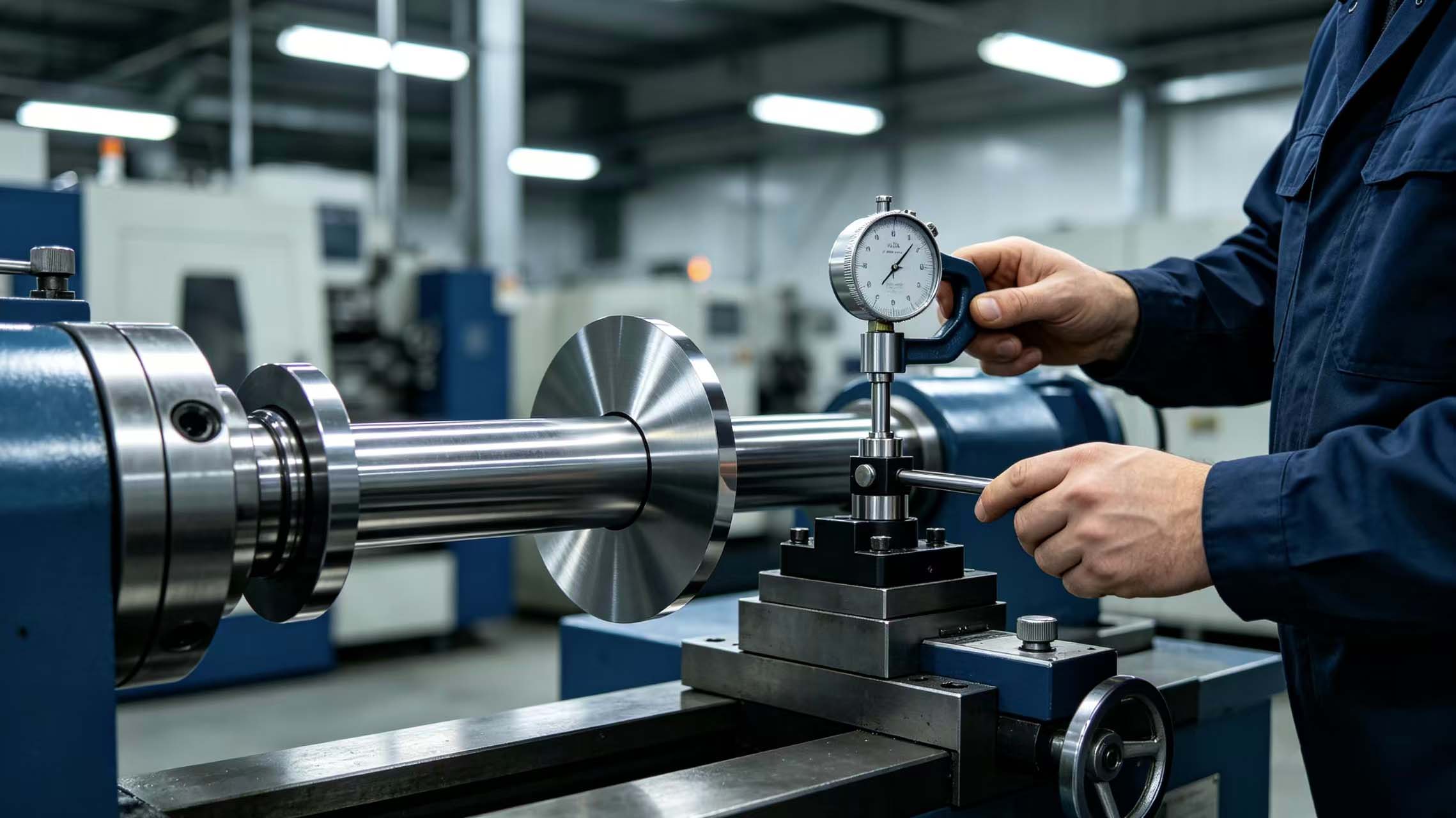
    In metal slitting operations, the roundness of slitter blades is a geometric accuracy indicator that is often overlooked but critically important. Excessive roundness deviation, no matter how hard the blade material or how sharp the edge, will result in periodic burrs, width fluctuations, and even wavy edges on the cut material. Mingbai Mechanical Tool Technology Co., Ltd., based on extensive on-site inspection data, quantifies the impact of roundness on shearing quality.   1. What Is Roundness?   Roundness refers to how close the outer diameter contour of a blade is to a perfect circle. It is typically evaluated using the least squares circle method or the minimum zone circle method, with the unit being micrometers (μm). For precision slitter blades, roundness requirements are usually between 2-5 μm. Excessive roundness deviation means the blade edge will produce radial runout during rotation.     2. How Does Roundness Affect Shearing Quality?   1. Causes periodic variation of burrs   When the roundness of circular blades deviates by 10μm, the gap between the upper and lower blades changes periodically with the rotation angle. At the smallest gap, the material is excessively squeezed, causing edge whitening and work hardening; at the largest gap, the material is stretched and torn, forming burrs. The result is a "wavy" distribution of burrs along the cut edge, visible to the naked eye.     2. Causes inconsistent shearing width   When slitting multiple strips, alloy blades with poor roundness cause width fluctuations in each strip. Experimental data shows: a blade with 0.01mm roundness produces width fluctuations of up to ±0.05mm; a blade with 0.002mm roundness controls width fluctuations within ±0.01mm.   3. Accelerates blade wear and chipping   Roundness deviation causes the blade edge to bear additional impact at local high points with each rotation. After long-term operation, stainless steel blades with poor roundness will show early wear or micro-chipping at the high points, reducing overall blade life by more than 30%.   3. Industry Grades of Roundness and Shearing Effects   According to industry standards, roundness can be divided into four grades. The ordinary grade has roundness ≤10μm, producing obvious burrs and large width fluctuations, suitable only for rough cutting or thick plates. The industrial grade has roundness ≤5μm, with acceptable burrs, suitable for general metal slitting. The precision grade has roundness ≤3μm, producing smooth cut edges with burr height controlled within 0.03mm, suitable for high-quality applications such as automotive and home appliance panels. The ultra-precision grade has roundness ≤2μm, achieving mirror-like cut edges with burrs ≤0.01mm, mainly used for high-end applications such as lithium battery electrodes and electronic foils. The high-speed slitter blade roundness produced by Mingbai Technology is controlled within ≤3μm, meeting precision slitting requirements.     4. Three Main Causes of Poor Roundness   1. Improper grinding process Using ordinary cylindrical grinders with insufficient precision of center holes or steady rests results in triangular or elliptical outer diameters. Roundness control in grinding of custom blades relies on high-precision CNC grinders.   2. Poor fit between bore and blade shaft The blade bore itself has poor roundness, or the clearance between the bore and shaft is too large, causing forced deformation after installation. Bore roundness of ultra-thin circular blades is particularly sensitive to installation accuracy.   3. Heat treatment deformation After quenching, the blade develops elliptical deformation without straightening or sizing treatment. Roundness retention of vacuum heat treated blades requires dedicated fixtures.   5. How to Measure Roundness?   Use a roundness measuring instrument or a coordinate measuring machine, collect at least 360 points on the blade's outer diameter, and calculate the roundness value using the least squares method. Every precision machine blade before shipment from Mingbai Technology is fully inspected with a roundness instrument, and an inspection report is provided.     6. Relationship Between Roundness and Other Accuracies   Roundness, concentricity, flatness, and surface roughness together determine the rotational accuracy of a blade. Poor roundness does not necessarily cause poor concentricity, but the combination of both worsens runout significantly. Flatness affects axial runout, while roundness affects radial runout; together they determine overall rotational accuracy. Surface roughness affects friction and adhesion, while roundness affects periodic stress; they are independent but complementary.   7. Mingbai Technology's Accuracy Guarantee   Mingbai Mechanical Tool Technology Co., Ltd. has a German-imported roundness measuring instrument capable of measuring blades up to 500mm in diameter with a resolution of 0.01μm. We provide measured data for the roundness of custom slitter blades for every blade, ensuring that every shipment meets precision grade standards.     8. Quick On-Site Judgment Methods for Users   If you do not have a professional roundness instrument, you can make a preliminary judgment using the following methods:   1. Mount the blade on the shaft and measure the radial runout of the outer diameter with a dial indicator. The runout value is approximately twice the roundness deviation (influenced by installation eccentricity).     2. Slit a long piece of material and check whether the burr height varies periodically with the rotation angle. 3. If burrs alternate between large and small in a regular pattern, the problem is very likely roundness.   Conclusion   The roundness of slitter blades is not an optional "precision indicator" but a hard threshold that directly determines shearing quality. The difference between 2μm and 10μm roundness is visible to the naked eye. Mingbai Mechanical Tool Technology Co., Ltd. insists on letting the data speak, ensuring that the roundness of every blade withstands inspection. Website: www.mingbaiblade.com
  • When Customizing Ultra-Thin Circular Blades, How to Ensure No Deformation During Heat Treatment?
    May 27, 2026
    When customizing deformation during heat treatment of custom ultra-thin circular blades is one of the most troublesome issues for engineers. Circular blades with a thickness of less than 3mm often warp, become oval, or develop wave-like distortion after quenching, which increases subsequent grinding allowance or even leads to direct scrap. Mingbai Mechanical Tool Technology Co., Ltd., based on years of experience in manufacturing ultra-thin blades, systematically analyzes the causes of deformation and control methods.   1. Three Major Deformation Modes of Ultra-Thin Circular Blades During Heat Treatment   Ultra-thin circular blades during the heat treatment process mainly experience three types of deformation:   · Warping deformation: The blade end face becomes dish-shaped or saddle-shaped, and flatness exceeds tolerance. · Oval deformation: The outer diameter becomes elliptical, destroying concentricity. · Dimensional shrinkage: The inner bore and outer diameter shrink unevenly, causing assembly difficulties.     2. Root Cause of Deformation: Superposition of Thermal Stress and Transformation Stress   Ultra-thin blades have poor rigidity and weak resistance to internal stress. Heat treatment deformation mainly comes from two sources:   · Thermal stress: Uneven expansion and contraction caused by temperature differences between the inside and outside of the blade during heating and cooling. · Transformation stress: During quenching, austenite transforms into martensite, with a volume expansion of about 4%, generating huge phase transformation stress.   For ultra-thin alloy blades and precision ultra-thin stainless steel blades, carbide segregation in the material itself can also exacerbate deformation.   3. Six Core Measures to Ensure No Deformation   1. Select low-deformation materials   Material is the fundamental factor for deformation. Choosing steel with good hardenability and low phase transformation expansion coefficient can fundamentally reduce deformation tendency. Mingbai Technology recommends materials for the material of custom ultra-thin circular blades including: Cr12MoV (vacuum refined), DC53, SKD11, and powder metallurgy high-speed steel. These materials have uniform carbide distribution, and heat treatment deformation can be reduced by 30%-50% compared to ordinary steel.   2. Use stress relief annealing as pretreatment   After rough machining and before finish machining, add a stress relief annealing process (temperature 550-650°C, hold for 2-4 hours) to eliminate internal stress introduced by cutting. This step is especially critical for ultra-thin mechanical blades and can effectively prevent warping during subsequent quenching.   3. Design dedicated heat treatment fixtures   Ultra-thin blades must use fixtures to constrain deformation during quenching. Common fixture types:   · Compression plate fixture: Two high-flatness heat-resistant steel plates pressing the blade with bolts to limit warping. · Bore rod fixture: A heat-resistant steel rod precisely fitted to the inner bore to prevent oval deformation. · Stacked combination fixture: Multiple blades stacked, separated by stainless steel foil, and compressed as a whole.   Mingbai Technology designs dedicated fixtures for each batch of vacuum heat treated ultra-thin circular blades with dedicated fixtures to ensure the blades remain flat throughout the quenching process.     4. Optimize quenching process parameters   · Step preheating: Use two-stage preheating at 650°C and 850°C to reduce heating temperature difference and lower thermal stress. · Control quenching temperature: Use the lower limit temperature (e.g., 980-1000°C for Cr12MoV instead of 1020°C) to reduce transformation stress. · Austempering: For high-precision ultra-thin blades can use austempering with thickness less than 1mm (isothermal in a salt bath at 250-350°C) to obtain lower bainite structure with minimal deformation.     5. Use compression tempering   During tempering, stress relief can also cause deformation. Continuing to press the blade in the fixture during tempering effectively maintains flatness. Do not open the fixture until the blade has cooled to room temperature after tempering.   6. Add cryogenic treatment   For custom ultra-thin slitter blades with cryogenic treatment requiring extremely high dimensional stability, add -150°C cryogenic treatment after quenching to promote full transformation of retained austenite and reduce deformation caused by subsequent transformation during use.   4. Mingbai Technology's Process Guarantees   Mingbai Mechanical Tool Technology Co., Ltd. has a complete ultra-thin circular blade heat treatment production line:   · Vacuum furnace with high-pressure gas quenching, temperature uniformity ±5°C · Self-developed combined anti-deformation fixtures · 100% flatness inspection after heat treatment for each blade (≤0.02mm/100mm) · Customizable hardness gradient: edge HRC60-62, blade body HRC45-50     5. User Verification Steps   After receiving ultra-thin circular blades, it is recommended to perform the following checks:   1. Place the blade flat on a granite surface plate and check flatness with a feeler gauge. 2. Measure axial runout and radial runout with a dial indicator. 3. If deformation exceeds tolerance, contact the manufacturer promptly; do not force installation.     6. Case Study   A lithium battery separator slitting factory custom-made ultra-thin circular blades with a thickness of 1.2mm. Previously, custom ultra-thin circular blades from three suppliers all had obvious warping (flatness 0.08mm). Mingbai Technology used the process of "stress relief annealing + compression quenching + compression tempering," achieving flatness controlled within 0.015mm. After installation, cutting was stable, and blade life increased by 40%.     Conclusion   Achieving no deformation in ultra-thin circular blades during heat treatment does not rely on luck, but on a systematic engineering approach of "material selection + fixture design + process control." Mingbai Mechanical Tool Technology Co., Ltd. is committed to providing custom ultra-thin circular blades with reliable products featuring controllable deformation. Website: www.mingbaiblade.com
  • Why Can the Price of the Same Model of Mechanical Blades from Different Manufacturers Differ by Three Times?
    May 26, 2026
    When purchasing high-precision custom blades, wear-resistant circular blades, or high-speed slitter blades, many users notice a phenomenon: blades of the same specification and same material can have quotes from different manufacturers that differ by three times or even more. Cheap blades seem to offer high cost-performance, but often have short life and many failures. Expensive blades make people wonder if they are paying a "stupidity tax." Mingbai Mechanical Tool Technology Co., Ltd. reveals the truth behind the price differences.   1. Raw Materials: The Same "Cr12MoV" Can Be Very Different   Many manufacturers claim to use Cr12MoV die steel, but even with the same Cr12MoV, the purity and carbide uniformity vary greatly between different steel mills and smelting processes. The first thing to consider is raw materials: low-priced blades may use recycled materials, non-standard materials, or low-purity steel from small mills, with internal defects such as segregation, inclusions, and porosity. High-hardness alloy blades made from such materials may barely meet hardness requirements but have poor toughness and are prone to chipping. In contrast, reputable manufacturers use electroslag remelted steel from major mills such as Baosteel and Fushun Special Steel, with uniform structure and fine carbides. High-quality steel provides significantly longer life and better stability. The difference in raw material cost can be 2-3 times, which is the first layer of price difference.     2. Heat Treatment: The Difference Between Having a "Vacuum Furnace" or Not Is Enormous   Heat treatment is the most "invisible" link in blade manufacturing. Low-priced blades use ordinary box furnaces or salt bath furnaces without atmosphere protection, resulting in severe surface decarburization; quenching temperatures are controlled by experience, leading to poor batch consistency; insufficient tempering cycles leave high residual stress. Vacuum heat treated precision machine blades of this kind may have inconsistent hardness and many internal micro-cracks. Reputable manufacturers use vacuum furnaces or protective atmosphere furnaces with computer-controlled precise temperatures; high-speed steel blades undergo 3-4 tempering cycles to fully relieve stress. The cost difference due to heat treatment quality can reach 30%-50%.     3. Grinding Precision: Micron Level vs. "Close Enough"   The edge angle, concentricity, and flatness of a blade directly determine cutting quality and life. Low-priced blades use ordinary tool grinders controlled by operator feel, with edge angle deviations of ±2° or more, and concentricity may exceed 0.02 mm. When installed, runout is large, vibration is severe, and burrs are serious. In contrast, reputable manufacturers use five-axis CNC grinders, with angle control within ±0.5° and concentricity ≤ 0.005 mm. Each wear-resistant circular blade shipped by Mingbai Technology is precisely inspected. The investment difference in grinding equipment is huge; one CNC grinder costs more than ten times that of an ordinary grinder.     4. Coating: With or Without Coating, and What Kind of Coating, Makes a Huge Difference   High-end blades typically use PVD coatings (TiN, TiAlN, DLC, etc.), which significantly reduce friction and improve wear resistance. Low-priced blades either have no coating or a very thin, non-professional coating that peels off within hours. Reputable manufacturers use imported coating equipment, with uniform coating thickness and strong adhesion. For materials such as stainless steel, corrosion-resistant stainless steel blades with high-quality coatings can greatly extend life. The coating cost difference per blade can be tens to hundreds of RMB, and the gap is significant in batch production.     5. Inspection and Quality Control: Full Inspection vs. Spot Check vs. No Inspection   Low-priced blades often have no inspection reports; hardness, angle, and runout all rely on "feel," and a batch may contain substandard products. Reputable manufacturers subject each blade to multiple tests for hardness, angle, runout, etc., before shipment, with traceable data. Mingbai Technology provides a complete inspection report for each high-speed slitter blade. The investment difference in quality control systems is also reflected in the price.     6. After-Sales Service: Someone to Turn to When Problems Arise vs. No One to Complain To   Higher-priced manufacturers typically provide value-added services such as technical consulting, on-site commissioning, and resharpening and recycling. Low-priced manufacturers often sell on a "one-off" basis, and you cannot find anyone when blade problems occur. Choosing a reliable supplier of high-precision custom blades results in lower long-term operating costs.   Mingbai Technology's Value Proposition   Mingbai Mechanical Tool Technology Co., Ltd. does not compete on the lowest price, but on "total cost of ownership." We firmly believe that one reasonably priced high-precision custom blade with stable life has a far lower total cost than three low-priced blades that fail frequently. We provide electroslag remelted steel from major mills, vacuum furnace heat treatment, CNC five-axis grinding, PVD coating, inspection reports for each blade, and 24/7 technical support.     Conclusion   A threefold price difference for the same model of blade reflects comprehensive gaps in raw materials, heat treatment, grinding, coating, quality control, and service. When selecting blades, do not look only at the unit price; look at the "cost per meter cut" and the "total cost of ownership." Mingbai Technology is committed to transparent processes and solid quality, so that every penny you spend is on the cutting edge. Website: www.mingbaiblade.com
  • Small Cracks Appear on the Surface of Circular Blades, Can They Still Be Used?
    May 22, 2026
    During slitting production, operators occasionally find small cracks on the surface of circular blades, slitter blades, or alloy blades. Some of these cracks are visible to the naked eye, while others can only be seen with a magnifying glass. When encountering such a situation, many people's first reaction is, "Can it still be used?" Based on materials science and field experience, Mingbai Mechanical Tool Technology Co., Ltd. provides you with judgment criteria and handling recommendations.   1. Two Types of Cracks: Surface Cracks vs. Deep Cracks   Surface micro-cracks: The depth is usually less than 0.05 mm, existing only in the blade's surface layer. Such cracks may be caused by grinding thermal stress, coating shrinkage stress, or minor impact. If the crack does not extend to the edge and the blade material is high-speed steel or a tough stainless steel blade, it may be temporarily usable under low-load conditions.   Deep cracks: Depth exceeds 0.1 mm, or extends from the surface inward. Such cracks often originate from excessive heat treatment stress, quenching micro-cracks, or long-term fatigue. Once a deep crack appears, the blade may fracture completely at any time and must be taken out of service immediately.     2. Main Causes of Cracks   1. Grinding burn: During resharpening, excessive feed rate or insufficient cooling causes localized overheating, producing grinding cracks. Such cracks are usually fine linear, distributed near the edge.   2. Heat treatment defects: Quenching temperature too high or inadequate tempering leaves excessive residual stress inside the blade, which slowly releases during use and causes cracking.   3. Fatigue cracks: Precision machine blades alternating cutting stress, and fatigue cracks initiate at stress concentration points such as keyways or hole edges.   4. Impact cracks: The blade receives an unexpected impact, such as from material joints or hard inclusions, causing localized chipping that extends into a crack.   5. Coating cracks: PVD coatings are hard but brittle. Under significant impact, the coating may crack while the substrate remains intact. Such cracks only affect coating life; the blade can continue to be used.   3. Three-Step Method to Determine Whether It Can Still Be Used   Step 1: Identify the crack location   · Crack on the edge → Dangerous, pieces may fly off during cutting, must be taken out of service. · Crack in a non-stressed area of the blade body, such as near the bore → Lower risk, can be used with short-term monitoring. · Crack on the end face but not extending to the outer diameter → Further depth inspection needed.     Step 2: Assess crack depth   · Observe with a 10x or higher magnifying glass. If the crack is as fine as a hair and does not penetrate the surface → it may be a surface crack. · Use dye penetrant inspection: clean the blade, apply penetrant, wipe off, then apply developer. If the developing line is continuous and clear → the crack is relatively deep. · Gently scrape with a fingernail or a metal piece. If you can feel a groove → the depth may exceed 0.1 mm.     Step 3: Decide based on working conditions   · Low speed, low load, non-safety-critical position → a surface crack may be temporarily usable, but increase inspection frequency. · High speed, high load, automated production line → any crack is recommended to be taken out of service. · Cutting valuable materials or involving personnel safety → replace immediately.   4. Crack Tolerance for Different Blade Materials   · High-speed steel circular blades: Good toughness, surface micro-cracks can be used short-term with monitoring. · Alloy blades (carbide): Very brittle, any crack is recommended to be taken out of service. Cracks in carbide propagate extremely quickly and easily lead to complete fracture.     · Stainless steel blades: Best toughness, relatively higher tolerance for surface cracks, but still need caution. · Coated blades: If only the coating is cracked and the substrate is intact, they can continue to be used, but the protective effect of the coating is reduced.   5. Emergency Handling for Cracked Blades   If you must temporarily use a custom blade with a crack, follow these rules:   1. Reduce cutting speed to below 60% of normal. 2. Decrease blade gap and overlap to reduce impact. 3. Stop every 30 minutes to check whether the crack has propagated. 4. Install a protective guard around the blade.   6. How to Prevent Cracks?   · Standardize resharpening: Send back to factory for CNC grinding, control feed rate and cooling to avoid grinding burn. · Optimize heat treatment: Choose suppliers with metallographic inspection capability to ensure adequate tempering. · Select appropriate material: For high-impact conditions, choose high-speed steel or tougher custom slitter blades. · Inspect before installation: Check each new blade's edge and surface with a magnifying glass.   7. Mingbai Technology's Recommendations and Inspection Services   Mingbai Mechanical Tool Technology Co., Ltd. recommends that any crack extending to the edge, or any crack deeper than 0.1 mm, should be taken out of service immediately. For cracks where the depth cannot be determined, you can send the blade back to Mingbai's laboratory for dye penetrant inspection or magnetic particle inspection. We will issue an inspection report clearly marking the crack's location, length, and depth, and give a conclusion of usable or scrap.   Conclusion   Small cracks do not mean immediate be declared worthless, but they should never be taken lightly. Location, depth, working conditions, and material together determine the fate of a cracked blade. When you are unsure, the safest choice is to take it out of service, inspect it, and consult a professional manufacturer. Mingbai Technology is willing to provide crack inspection and risk assessment services for you. Website: www.mingbaiblade.com
  • After Frequent Resharpening of Slitter Blades, Will Precision Drop off a Cliff?
    May 20, 2026
    In slitting production, slitter blades and circular blades become dull after a period of use, and resharpening is a routine method to restore sharpness. However, many users worry: after a few resharpenings, will the blade be ruined? Will precision suddenly drop significantly? Based on years of resharpening experience, Mingbai Mechanical Tool Technology Co., Ltd. reveals the answer: resharpening itself does not cause a cliff-like drop in precision. What really affects precision is the method of resharpening and the control of resharpening frequency.   1. The Essence of Resharpening: Removing the Worn Layer, Restoring Geometry   The essence of blade dulling is edge wear that rounds the edge or causes micro-chipping. Resharpening removes this fatigue layer through grinding and re-forms a sharp edge geometry. A properly designed precision machine blade has an effective thickness much greater than the amount of wear per single use. In theory, as long as the resharpening method is correct, a blade can be resharpened many times without losing precision.     2. The Real Reasons for a Cliff-Like Drop in Precision   1. Insufficient precision of the resharpening equipment   Using ordinary tool grinders or hand-held grinders cannot guarantee edge angle, concentricity, or flatness. One incorrect resharpening can worsen the radial runout of a blade from 0.005 mm to 0.03 mm, causing precision to collapse instantly.     2. Not controlling the amount of material removed per sharpening   If the amount removed each time is too large, for example, exceeding 0.2 mm, it changes the blade's outer diameter, causing mismatch in the gap and overlap between upper and lower blades, affecting cut quality.   3. Not resharpening paired blades together   For upper and lower circular blades used as a pair, if only one is resharpened and the other remains unchanged, the difference in outer diameter between the two will the original gap setting.   4. Exceeding the allowable number of resharpenings   Each alloy blade or stainless steel blade has a certain blade body thickness. When the cumulative material removal approaches 10% to 15% of the blade body thickness, the blade rigidity decreases, and further resharpening may cause deformation or cracking.   3. Precision Can Be Maintained After Correct Resharpening   Using CNC precision grinders and factory resharpening performed according to specifications, blade precision can be almost completely restored:   · Edge angle: restored to within ±0.5° of the original factory specification · Concentricity: still controllable within 0.005 mm · Surface finish: can be restored to Ra ≤ 0.2 μm   Mingbai Technology's data shows that a custom blade correctly resharpened 3 to 5 times can still maintain more than 90% of the cutting quality and life of a new blade.   4. How to Avoid Precision Loss Caused by Resharpening?     1. Choose professional factory resharpening   Do not use angle grinders or belt sanders for on-site sharpening. Factory resharpening with five-axis CNC grinders is necessary to guarantee angle and runout.     2. Control the amount of material removed per sharpening   The amount removed per resharpening should be controlled between 0.05 mm and 0.10 mm, removing only the worn layer. Do not remove too much.     3. Establish a resharpening record   Keep a record for each slitter blade of the cumulative number of resharpenings and cumulative material removed. When the cumulative removal approaches 10% of the blade thickness, consider replacing the blade.   4. Resharpen paired blades together   Upper and lower blades should be sent for resharpening as a pair, or ensure the outer diameters match after resharpening.   5. Reset the gap after each resharpening   After each resharpening, because the outer diameter changes slightly, you must  measure the side gap between upper and lower blades with a feeler gauge and adjust accordingly.   5. When Should You Stop Resharpening?   When the following conditions occur, the blade is near the end of its life and should be replaced:   · The cumulative number of resharpenings exceeds 5 to 6 times, depending on the original thickness. · After resharpening, the edge still has visible chipping or cracks. · After resharpening and installation, runout still exceeds tolerance, for example, above 0.01 mm. · The blade shows overall deformation or end face wear.   6. Mingbai Technology's Resharpening Services   Mingbai Mechanical Tool Technology Co., Ltd. provides professional factory resharpening services. Each circular blade, alloy blade, or custom slitter blade comes with an inspection report after resharpening, showing before-and-after comparison of angle, runout, and edge radius. We guarantee that precision after resharpening is no less than 95% that of a new blade.     7. Case Study   An auto parts factory continuously resharpened a slitter blade 5 times, removing 0.08 mm each time. After the fifth resharpening, the cut quality still met requirements, and the cumulative life reached 2.8 times that of a new blade. In contrast, another blade from the same factory that was sharpened on-site with an angle grinder was ruined in one go.   Conclusion   Resharpening does not cause a cliff-like drop in blade precision. Incorrect resharpening does. As long as you use a professional manufacturer, control the material removal amount, and keep a record of the number of resharpenings, a custom blade can be resharpened many times, achieving a total life of 2 to 3 times that of a new blade. Mingbai Technology is willing to be your partner in managing the entire life cycle of your blades. Website: www.mingbaiblade.com
  • When Customizing Blades, How to Accurately Describe the Cutting Feel Requirement to the Manufacturer?
    May 19, 2026
    When customizing custom blades, circular blades, or slitter blades, many users express a vague but very important requirement: "the feel should be light" or "it should cut smoothly." However, cutting feel is a subjective concept that varies greatly among different operators. If this feeling cannot be translated into quantifiable technical parameters, it is difficult for the manufacturer to precisely meet your needs. Mingbai Mechanical Tool Technology Co., Ltd. provides you with a practical method to convert cutting feel into engineering language.   1. What Is Cutting Feel?   Cutting feel is the state of the cutting process that an operator perceives through a combination of hearing, touch, and vision during equipment operation or manual cutting. A good cutting feel typically:the cutting sound is stable and low-pitched, the feed resistance is uniform, the cut edge is smooth and burr-free, and no vibration is transmitted to the handle or control panel.   2. Converting Cutting Feel into Quantifiable Parameters     Lightness corresponds to edge sharpness. A light cutting feel means low cutting resistance, which mainly depends on the edge angle and edge radius of precision machine blades. The smaller the edge angle, for example 15 to 20 degrees, the lighter and faster the cutting. The smaller the edge radius, for example no more than 0.005 millimeters, the easier the penetration. When describing to the manufacturer, instead of saying "light," say "edge angle 18 degrees plus or minus 0.5 degrees, edge radius no more than 0.005 millimeters, surface polished to Ra no more than 0.2 micrometers." Smoothness corresponds to surface finish and coating. A smooth cutting feel means no hesitation or stickiness, which depends on the surface finish and friction coefficient of the blade. The smoother the surface, the more smoothly chips are evacuated. DLC or molybdenum disulfide coatings can significantly reduce the friction coefficient. When describing to the manufacturer, instead of saying "smooth," say "mirror polish on the edge and rake face, Ra no more than 0.1 micrometers, DLC coating recommended."     No vibration corresponds to blade precision and dynamic balance. A vibration-free cutting feel means a stable cutting process, which depends on the concentricity, flatness, and dynamic balance grade of circular blades. When concentricity is no more than 0.005 millimeters, radial runout is small. The dynamic balance grade should reach G2.5 or higher. When describing to the manufacturer, instead of saying "no vibration," say "concentricity no more than 0.003 millimeters, dynamic balance grade G2.5, runout inspection report provided for each blade."     3. Using Trial Cut Samples Instead of Verbal Descriptions   The most accurate way to communicate is to provide a "cutting feel standard sample." You can take a piece of material that feels ideal to you, meaning material that has been cut with a blade you are satisfied with, mark the cut edge with a label saying "satisfactory feel," and then send it to the manufacturer, asking them to reverse-engineer the blade parameters based on this cut edge effect. Mingbai Technology can reverse-engineer the edge angle, passivation value, and surface finish from the cut edge morphology of the sample you provide, achieving precise replication.     4. Describing Working Conditions and Letting the Manufacturer Calculate for You   If you are not familiar with technical terms such as angle and radius, you can describe the working conditions in detail, and Mingbai engineers will calculate the optimal parameters for you. Information to provide includes: material type, grade, and thickness; equipment type, whether manual or automatic, and speed range; specific description of cutting feel, for example "my wrist does not get tired when cutting thick plates" or "the handle does not go numb at high speed"; and a comparison of current satisfactory or unsatisfactory cutting feel.   5. Common Cutting Feel Problems and Corresponding Parameter Adjustments   When the cutting feel problem is heavy and laborious cutting, the possible cause is an excessively large edge angle. You should ask the manufacturer to reduce the wedge angle by 2 to 3 degrees and reduce the edge radius.   When the cutting feel problem is stickiness or stringing, the possible cause is a rough surface or missing coating. You should ask the manufacturer for mirror polishing and the addition of a DLC coating.   When the cutting feel problem is strong vibration or hand numbness, the possible cause is poor concentricity or bad dynamic balance. You should ask the manufacturer for concentricity no more than 0.005 millimeters and a G2.5 dynamic balance grade.   When the cutting feel problem is a sharp, piercing sound, the possible cause is an excessively small clearance angle or improper gap. You should ask the manufacturer to increase the clearance angle by 2 degrees and recalibrate the gap.   When the cutting feel problem is large burrs on the cut edge, the possible cause is a dull edge or uneven angle. You should ask the manufacturer to reduce the edge radius and check angle uniformity.   6. Mingbai Technology's Feel Replication Service   Mingbai Mechanical Tool Technology Co., Ltd. offers a special service called Feel Replication. You simply send an old blade with satisfactory cutting feel or a cut edge sample, and our engineers use coordinate measuring machine measurements, profilometer analysis, and cutting tests to reverse-engineer the complete blade parameters and produce identical custom slitter blades. This service has helped hundreds of customers solve the problem of "the feel changes when I change suppliers."     7. Case Study   A leather cutting workshop that performed manual cutting had operators who were extremely sensitive to cutting feel. After their original source of circular blades was discontinued, they tried three different suppliers and were unsatisfied with all of them, saying the blades were too heavy and did not follow the hand. Mingbai Technology engineers conducted on-site testing and measured the original blade's edge angle at only 16 degrees and edge radius at only 0.003 millimeters. After reproduction according to these parameters, the cutting feel was completely restored, and the operators said, "This is the feeling."   Conclusion   Cutting feel is not a mystery; it is a quantifiable engineering parameter. As long as you can communicate with the manufacturer using the four terms of angle, radius, surface finish, and concentricity, or directly provide a sample, you can have custom blades that perfectly replicate the cutting feel you desire. Mingbai Mechanical Tool Technology Co., Ltd. is willing to be the translator for your cutting feel requirements. Website: www.mingbaiblade.com
  • When Mechanical Blades Make Unusual Noises During Use, Is It an Installation Problem or a Material Problem?
    May 18, 2026
    On slitting production lines, when circular blades, slitter blades, or alloy blades suddenly make unusual noises such as clicking, squeaking, or humming during operation, it is an alarming signal. Many operators first think, "The blade quality is poor." However, based on hundreds of on-site diagnoses, Mingbai Mechanical Tool Technology Co., Ltd. has found that about 60% of unusual noise roots are related to installation, 30% are related to working conditions, and less than 10% are truly material problems. This article helps you quickly identify the source of unusual noises and provides solutions.   1. Three Typical Types of Unusual Noises and Their Corresponding Causes   1. Clicking metal impact sound   This type of sound is usually rhythmic and synchronized with the blade shaft rotation speed. Common causes include: the gap between upper and lower circular blades is too small, causing the edges to rub and squeeze against each other; the blade is eccentrically installed or the fit between the bore and blade shaft is too loose, causing an impact with each rotation; the blade edge has chipping, and the chipped area impacts the material during rotation.     2. Squeaking high-pitched friction sound   This type of sound is continuous and high-frequency. Common causes include: insufficient lubrication and cooling, causing dry friction between the blade and material; the blade clearance angle is too small, causing excessive contact area between the blade body and material; the material is sticky such as self-adhesive labels or aluminum foil, and adhered material rubs between the edge and the material.   3. Humming low-pitched resonance sound   This type of sound changes with rotation speed and suddenly increases at specific speeds. Common causes include: poor dynamic balance of the blade or blade shaft; loose components on the equipment resonating at specific frequencies; inconsistent blade gaps in multi-blade slitting systems.   2. Quick Diagnosis: Is It an Installation Problem or a Material Problem?   Step 1: No-load test   Remove the material and run the blades with no load. If the unusual noise disappears, the problem is with the material or cutting parameters. If the unusual noise persists, the problem is with blade installation or the blade itself.   Step 2: Interchange test   Move the precision machine blade that is making the unusual noise to another normal machine and run it. If the unusual noise follows the blade, the problem may be blade material or manufacturing. If the unusual noise stays with the original machine, the problem is installation or equipment related.   Step 3: Gap and runout inspection   Use a feeler gauge to measure the gap between upper and lower blades. Is it within 5% to 10% of material thickness? Use a dial indicator to measure blade radial runout. Is it 0.005 millimeters or less?     3. Common Installation Problems and Solutions   If the gap is too small, the phenomenon is a slight friction sound even during no-load operation. The solution is to reset the gap to 5% to 10% of material thickness.   If the blade is eccentric, the phenomenon is a click sound once per rotation. The solution is to check the fit between the bore and blade shaft and clean the mounting surfaces.   If the blade shaft is bent, the phenomenon is excessive runout with unusual noise increasing with speed. The solution is to repair or replace the blade shaft.   If the nut is loose, the phenomenon is intermittent sound. The solution is to tighten with a torque wrench to the standard torque value.   If the spacer has poor parallelism, the phenomenon is blade tilt with single-side contact. The solution is to replace with a high-precision spacer.   4. Common Material or Blade Problems and Solutions   If the edge is chipped, the phenomenon is an impact sound when the chipped position rotates into contact. The solution is to send back to the factory for resharpening or replace the blade.     If the hardness is uneven, the phenomenon is sound varying in intensity. The solution is to check heat treatment quality and change suppliers.   If the coating is peeling, the phenomenon is gradually increasing friction sound. The solution is to recoat or replace with custom slitter blades.   If the blade is deformed, the phenomenon is excessive axial runout. The solution is to check storage methods and avoid stacking.   5. Working Condition Related Unusual Noises and Adjustments   For large material thickness fluctuations, the blade experiences instantaneous force changes, producing irregular impact sounds. The solution is to stabilize incoming material quality or choose stainless steel blades with better toughness.   For insufficient lubrication, a high-pitched friction sound accompanies heated cut edges. The solution is to increase cutting fluid flow and check nozzle angles.     For excessive speed, a humming resonance sound appears at specific speeds. The solution is to increase or decrease speed by 10% to 15% to avoid the resonance zone.   6. When Can It Be Determined as a Material Problem?   Only after eliminating all the following factors can a material problem be suspected: installation gap, runout, and parallelism are all within specification; the blade has no chipping or deformation; lubrication is sufficient and material is stable; another blade from the same batch produces the same unusual noise; and a blade from another brand eliminates the unusual noise. In this case, contact the supplier for hardness and metallographic testing.   7. Mingbai Technology's Diagnostic Services   Mingbai Mechanical Tool Technology Co., Ltd. provides free remote diagnostic services for unusual noises. Simply record a sound video of the equipment in operation, and our engineers can preliminarily determine the type of unusual noise and possible causes. For complex cases, on-site inspection can be arranged.     Conclusion   Unusual noises from mechanical blades are not mysterious; they are fault signals with observable patterns. Most unusual noises originate from installation or working conditions, not blade material. Follow the steps in this article to check each possibility, and most problems can be resolved quickly. Mingbai Technology is ready to use its professional experience to help you understand the language of your blades. Website: www.mingbaiblade.com
  • For Circular Blades, Should You Choose High-Speed Steel or Carbide?
    May 15, 2026
    When customizing circular blades, material selection is the core issue determining blade performance and cost. High-speed steel and carbide are the two most commonly used materials, but their characteristics, applicable scenarios, and prices differ greatly. Choose correctly, and you achieve twice the result with half the effort. Choose incorrectly, and blade life is halved or equipment is damaged. Mingbai Mechanical Tool Technology Co., Ltd., based on years of material application data, provides you with a detailed comparison of the advantages and disadvantages of these two materials to help you make a reasonable choice.     1. High-Speed Steel Circular Blades: Toughness is King   High-speed steel is a tool steel alloyed with elements such as tungsten, molybdenum, chromium, and vanadium. Representative grades include M2, M35, M42, and ASP2053.     Advantages: High-speed steel has excellent toughness, strong impact resistance, and is not prone to chipping. It is particularly suitable for working conditions with impact loads, such as when material thickness fluctuates greatly or when there are joints. Its resharpening ability is very good, with little performance degradation after multiple resharpening cycles, resulting in long total life. In terms of cost, for the same specifications, the price of high-speed steel is about one-third to one-half that of carbide. Additionally, high-speed steel is easy to machine and can be made into complex-shaped custom blades and special-shaped blades.   Disadvantages: High-speed steel has relatively insufficient wear resistance. When cutting highly abrasive materials such as fiberglass or silicon steel, it wears relatively quickly. Its red hardness is limited; when cutting at high speeds, if the temperature exceeds 550-600°C, it will soften.   Applicable scenarios: High-speed steel is suitable for slitting common metals such as ordinary carbon steel, stainless steel, copper, and aluminum. It is suitable for working conditions with large material thickness fluctuations or joints, for applications requiring frequent resharpening, and for mechanical blades with complex shapes.   2. Carbide Circular Blades: Wear Resistance is King   Carbide is a composite material made from tungsten carbide and a binder phase such as cobalt through powder metallurgy. Representative grades include YG6X, YG8, YG15, and KD20.     Advantages: Carbide has ultra-high hardness, reaching HRA89-93.5, equivalent to HRC70-78, with excellent wear resistance. Its red hardness is very good, maintaining hardness at high temperatures of 800-1000°C, making it suitable for high-speed cutting. Under the same working conditions, the life of carbide blades is typically 3 to 10 times that of high-speed steel.   Disadvantages: Carbide has poor toughness, is very brittle, and has weak impact resistance. It is prone to chipping when encountering hard spots or sudden thickness changes. Cost is high, with material prices and processing difficulty far exceeding those of high-speed steel. Resharpening is difficult, requiring specialized diamond grinding wheels, and the resharpening cost is high.   Applicable scenarios: Carbide is suitable for highly abrasive materials such as silicon steel sheets, fiberglass boards, and composite materials. It is suitable for high-speed slitting exceeding 150 meters per minute, for ultra-thin materials below 0.3 millimeters requiring extremely sharp and wear-resistant edges, and for automated production lines requiring ultra-long life and reduced blade change frequency.   3. Comparison of Characteristics   In terms of hardness, high-speed steel ranges from HRC58-67, while carbide ranges from HRA89-93.5, equivalent to HRC70-78, making carbide significantly harder. In impact resistance, high-speed steel is excellent, while carbide is poor. In wear resistance, high-speed steel is good, while carbide is excellent. In red hardness, high-speed steel can only withstand 550-600°C, while carbide can withstand 800-1000°C. In resharpening ability, high-speed steel is easy and can be done with ordinary grinding wheels, while carbide is difficult and requires diamond wheels. In cost, high-speed steel is low, while carbide is high, approximately 3 to 5 times that of high-speed steel. In typical life, using high-speed steel as a baseline of 1, carbide can achieve 3 to 10 times that life.     4. How to Choose?   First, consider whether the working conditions involve impact. If material thickness fluctuation exceeds plus or minus 10 percent, or if the material has weld marks or joints, or if equipment rigidity is insufficient, high-speed steel should be chosen.   Second, consider material abrasiveness. For silicon steel, fiberglass, and composite materials, carbide should be chosen. For continuous cutting of stainless steel, both are acceptable, but high-speed steel offers better cost performance. For ordinary carbon steel, copper, and aluminum, high-speed steel is sufficient.   Finally, consider speed and life requirements. If speed exceeds 150 meters per minute, or if an automated production line requires reduced blade change frequency, carbide should be chosen. If the budget is limited and frequent blade changes are acceptable, high-speed steel is a reasonable choice.     5. Mingbai Technology's Material Combination Solutions   We offer a variety of material options including alloy blades, stainless steel blades, and circular blades, as well as customized composite solutions. Carbide-tipped circular blades use a high-speed steel body with a carbide-tipped edge, combining toughness and wear resistance. Coated high-speed steel applies PVD coatings such as TiAlN or AlCrN to a high-speed steel substrate, increasing wear resistance by 2 to 3 times with excellent cost performance. Gradient carbide uses high cobalt content at the edge for increased toughness and low cobalt content in the body for high hardness, balancing chip resistance and wear resistance.   6. Case Study   A silicon steel sheet slitting plant originally used high-speed steel circular blades and changed blades every 2 days. After switching to carbide alloy blades, the blade change interval extended to 15 days. Although the per-blade cost increased, total downtime decreased by 70 percent, and overall costs dropped by 45 percent.   Another wire and cable plant mistakenly used carbide blades for slitting copper strip. When encountering material joints, severe chipping occurred. After switching back to high-speed steel custom blades, the problem was immediately resolved.   Conclusion   There is no absolute "which is better" between high-speed steel and carbide; only "which is more suitable." The toughness, resharpening ability, and low cost of high-speed steel make it the first choice for most conventional working conditions. The wear resistance and red hardness of carbide are irreplaceable in highly abrasive and high-speed scenarios. Mingbai Mechanical Tool Technology Co., Ltd. can provide a free recommendation for the optimal material solution based on your specific material, equipment, and budget. Website: www.mingbaiblade.com

  • What Standard Should Be Used to Adjust the Side Gap Between Upper and Lower Slitter Blades?
    May 12, 2026
    In metal slitting operations, the side gap between upper and lower slitter blades is one of the most critical process parameters. If the gap is too large, the cut edge burrs become jagged. If the gap is too small, the blades rub against each other, generating heat and even causing chipping. Many operators adjust it by feel, resulting in inconsistent product quality. Mingbai Mechanical Tool Technology Co., Ltd., based on domestic and international standards and years of practice, clarifies the logic and method for setting the side gap.   1. What Is the Essence of the Side Gap?   The side gap is the horizontal distance between the cutting edges of upper and lower circular blades. Its purpose is to provide space for the lateral deformation that occurs when the material is sheared. If the gap is too small, the material is excessively squeezed, causing edge whitening and work hardening. If the gap is too large, the material is stretched and torn, increasing burrs.   The ideal side gap allows the material to undergo slip and fracture rather than squeeze and tear when the edge penetrates.     2. General Rule of Thumb: The 5% Rule   For most materials, the initial gap can be set using the following formula: Side gap = Material thickness × (5% to 10%)   · Hard and brittle materials such as silicon steel and high-carbon steel: Use the upper limit of 8% to 10% to avoid impact chipping of the edge. · Soft and tough materials such as low-carbon steel, copper, and aluminum: Use the lower limit of 5% to 7% to reduce burrs. · Ultra-thin materials below 0.3 millimeters: Use 3% to 5% to prevent edge curling.   For example, for 2.0 millimeter thick ordinary steel plate, set the initial gap to 2.0 × 5% = 0.10 millimeters. For 0.5 millimeter silicon steel, set the gap to 0.5 × 10% = 0.05 millimeters. 3. Detailed Recommendations for Different Materials   Ordinary carbon steel such as Q235 and SPCC: Take 5% to 8% of material thickness. Use the lower limit for thin materials and the upper limit for thick materials.   Stainless steel such as 304 and 430: Take 6% to 10%. Stainless steel has severe work hardening, so a larger gap reduces friction between the edge and the material.   Silicon steel: Take 8% to 12%. The material is hard and brittle, requiring a larger gap to reduce impact.   Copper and aluminum: Take 4% to 6%. Soft metals are sensitive to gap; too large a gap causes edge stringing.   High-strength steel: Take 8% to 10%. Balancing hardness and toughness, the gap should not be too small.   For alloy blades or stainless steel blades, since the material itself is harder, the gap can be reduced by 5% to 10%.     4. Practical Steps for Gap Adjustment   Step 1: Zeroing – Bring the upper and lower blades together until they just make light contact, feeling slight friction. At this point, the gap is zero.   Step 2: Initial setting with feeler gauge – Based on material thickness and the formula, select a feeler gauge of the corresponding thickness. Insert it between the upper and lower blades, loosen the blade holder lock nut, and adjust until the feeler gauge can be pulled out with slight resistance.     Step 3: Trial cut verification – Slit a section of material at normal speed and inspect the cut edge with a magnifying glass.   · Small, uniform burrs indicate the gap is appropriate. · Burrs on one side indicate axial misalignment between upper and lower blades; adjust the axial position. · Large burrs with tearing marks indicate the gap is too large; reduce by 0.01 to 0.02 millimeters. · Whitened edge with powder indicates the gap is too small; increase by 0.01 to 0.02 millimeters.     Step 4: Record keeping – Record the optimal gap value on the process card for direct use next time.   5. Common Misconceptions and Corrections   Misconception 1: Using the same gap for different materials. Correction: Every time you change materials, you must readjust the gap.   Misconception 2: Only using your eyes, never using a feeler gauge. Correction: A gap of 0.05 millimeters cannot be distinguished by the naked eye; tools must be used.   Misconception 3: Not checking the gap again after setting it. Correction: After blade resharpening, the outer diameter decreases, and the gap changes accordingly, requiring resetting.   6. Mingbai Technology's Technical Recommendations   For precision machine blades and custom slitter blades, we recommend:     · For initial installation of new blades, set the gap at 6% of material thickness. · After each resharpening, because the outer diameter decreases by approximately 0.1 to 0.2 millimeters, the gap should be reduced by 0.01 to 0.02 millimeters accordingly. · For high-speed slitting lines exceeding 100 meters per minute, reduce the gap by 10% to 15% compared to the conventional value to reduce vibration.   7. Case Study   A home appliance panel processing plant was cutting 1.5 millimeter galvanized steel with a constant gap of 0.05 millimeters, resulting in severe burrs on the cut edge. After an on-site inspection, Mingbai engineers reset the gap to 1.5 × 6% = 0.09 millimeters according to the formula. The burrs disappeared immediately, and blade life increased from 2 weeks to 5 weeks.   Conclusion   Adjusting the side gap of slitter blades is not mysterious; it is a science with evident rules. Remember the starting point of "5% to 10% of material thickness," measure with a feeler gauge, verify with trial cuts, and solidify the results with records. Mingbai Mechanical Tool Technology Co., Ltd.'s engineers are always available to provide on-site gap optimization services. Website: www.mingbaiblade.com
  • When Customizing Special-Shaped Blades, What Pitfalls Exist in Drawing Specifications for Edge Angle?
    May 11, 2026
    When customizing custom blades, circular blades, or slitter blades, the specification of edge angle is the most error-prone step and the most likely to cause subsequent disputes. A seemingly clear "30 degrees" can mean completely different things to different manufacturers or technical personnel. Based on years of experience processing special-shaped blade orders, Mingbai Mechanical Tool Technology Co., Ltd. outlines five major pitfalls in specifying edge angle on drawings and how to avoid them.   1. Pitfall One: Specifying Only the Angle Without Direction   The edge angle is a three-dimensional concept, including three directions: wedge angle, rake angle, and clearance angle. Many drawings only state "edge angle 30 degrees" without specifying which angle.   Wedge angle is the angle between the two edge faces, determining the balance between sharpness and strength. Rake angle is the angle between the edge face and the vertical plane, affecting chip flow direction. Clearance angle is the angle between the edge face and the machined surface, affecting friction.     Correct specification: Draw an enlarged local cross-sectional view, clearly marking the values for wedge angle, rake angle, and clearance angle. For alloy blades or stainless steel blades, the three angles each have different functions and must not be confused.   2. Pitfall Two: Not Specifying Angle Tolerance   The edge angle is not an absolute precise value; it requires an allowable range of variation. Without specified tolerance, the manufacturer defaults to general standards such as plus or minus 2 degrees, which may not meet your actual needs.     Consequence: The 25-degree wedge angle you expect may end up ground to 27 degrees, significantly increasing cutting resistance.   Correct specification: State the angle tolerance, for example "wedge angle 25 degrees plus or minus 0.5 degrees." For precision machine blades, a tolerance of no more than plus or minus 0.5 degrees is recommended.   3. Pitfall Three: Ignoring the Edge Radius, or Passivation Value   The edge angle only describes the angle between the two edge faces but does not describe the microscopic form of the edge tip. The same 25-degree wedge angle can be ground to an extremely sharp point with a radius of 0.005 millimeters or less, or to a micro-passivated radius of 0.02 millimeters. The cutting performance and life differ vastly between these two.     Consequence: You want a wear-resistant micro-passivated edge, but the manufacturer produces an extremely sharp edge, leading to frequent chipping.   Correct specification: Add a specification for "edge radius R" on the drawing. For custom slitter blades cutting ordinary steel, an R value of 0.01 to 0.02 millimeters is appropriate.   4. Pitfall Four: Not Specifying the Measurement Location on the Edge   For special-shaped blades, the edge angle may vary along the profile. If you only specify "edge angle 30 degrees," the manufacturer cannot determine whether to measure at the highest point, the lowest point, or another specific location on the edge.     Consequence: The finished blade may achieve the specified angle at only one point, with significant deviations elsewhere.   Correct specification: State that "the edge angle is the wedge angle in the normal cross-section at each point along the profile." Provide a 3D model if necessary.   5. Pitfall Five: Confusing Initial Edge Angle with Angle After Re-sharpening   Blades require multiple re-sharpenings during their service life. Whether the edge angle changes after each re-sharpening depends on the blade's geometric design.     Problem: If the drawing specifies only the initial angle, but the blade is designed as a re-sharpenable type, the angle becomes smaller after re-sharpening, affecting cutting performance.   Correct specification: Clearly state that "this angle is for the initial condition, and the angle change after up to three re-sharpenings shall not exceed plus or minus 1 degree."   6. How to Avoid These Pitfalls?   First, provide cross-sectional views. Draw at least one enlarged local cross-section of the edge region, marking all angles and radius.   Second, reference Mingbai standards. We can provide a standard template for specifying edge angles; simply fill it out according to the template.   Third, consider a trial sample. For complex special-shaped circular blades, it is recommended to make one sample blade first to verify the angle effect.     Mingbai Technology's Technical Support   We offer drawing review services for special-shaped blades, slitter blades, and mechanical blades. Before you formally place an order, our engineers will check whether the angle specifications are complete and reasonable, and suggest modifications.   Conclusion   The edge angle is the core code for blade performance. Unclear specifications can lead to blades that are unsuitable, or even direct scrapping. Mingbai Mechanical Tool Technology Co., Ltd. recommends that you spend 10 minutes confirming the edge angle specification details with our technical team before placing your order. Fill in the pitfalls, and your customization will succeed on the first try. Website: www.mingbaiblade.com
  • Why Does Your Mechanical Blade Always Fall Short of Its Expected Life by Half?
    May 08, 2026
    In slitting workshops, a common and puzzling phenomenon is this: the same circular blades or slitter blades that last three months in another factory barely survive six weeks in yours. Many users first think, "This batch of blades is poor quality." However, after tracking and analyzing over a hundred cases, Mingbai Mechanical Tool Technology Co., Ltd. found that more than 70% of short-life cases are not rooted in the blades themselves, but in hidden systemic factors related to equipment, operation, or working conditions. This article reveals six invisible killers.   1. Blade Gap is Close Enough   The gap between upper and lower circular blades is the most sensitive parameter affecting shearing force. Many operators set it by feel and never verify it with a feeler gauge.     · Gap too small: The upper and lower blade edges rub and squeeze against each other, generating micro-cracks. After hours of operation, the edge shows powdery spalling. · Gap too large: The material is stretched and torn rather than sheared, and the edge bears additional impact loads, accelerating wear.   Correct practice: Every time you change blades or materials, use a feeler gauge to measure the blade gap. The general rule is 5% to 10% of material thickness. Use the lower limit for hard, thin materials and the upper limit for soft, thick materials.   2. Runout Never Checked After Blade Installation   The radial runout and axial runout of precision machine blades directly determine wear uniformity. When runout exceeds tolerance, the blade edge at the highest point bears cutting forces several times the average value with each revolution.     · Phenomenon: Edge wear appears wavy, with local regions dulling quickly, shortening overall life. · Standard: After installation, radial runout of alloy blades should be 0.005 mm or less, and axial runout 0.008 mm or less.   Solution: Measure with a dial indicator after installation. If out of tolerance, check whether the blade shaft is bent or if there are burrs in the bore.   3. Treating Sharpness as the Only Standard   To pursue extreme cut quality, some users demand custom blades with edge angles less than 15 degrees. An overly sharp edge lacks sufficient support and is prone to micro-chipping when encountering hard spots or thickness fluctuations in the material.     · Manifestation: Tiny, nearly invisible nicks appear on the edge, then accelerate wear, causing a sudden drop in life. · Data: Reducing the edge angle from 25 degrees to 15 degrees increases sharpness by about 40%, but decreases impact resistance by about 60%.   Mingbai recommendation: Choose a reasonable angle based on the material. Use 25 to 30 degrees for ordinary steel, 18 to 22 degrees for soft metals, and apply micro-passivation with radius of 0.01 to 0.02 millimeters.   4. Neglecting the Importance of Lubrication and Cooling   Dry cutting or insufficient cooling is one of the biggest killers of blade life.     · Tempering risk: When the edge temperature of high-speed steel exceeds 550 degrees Celsius, hardness drops sharply. · Chip adhesion risk: Materials like aluminum and copper adhere to the edge at high temperatures, forming a built-up edge that alters the edge geometry.   Correct practice: Ensure adequate cutting fluid and that it is directed at the cutting entry zone. For high-speed slitting, use oil mist lubrication at 5 to 20 milliliters per hour.   5. Unstable Incoming Material Quality Damages the Blade   If upstream material thickness fluctuates by more than plus or minus 10%, or if the material edge has hard spots, weld marks, or inclusions, even the best stainless steel blades or custom slitter blades cannot withstand it.     · Consequence: The blade suffers instantaneous impact chipping when passing through thick spots or hard points. · Diagnosis: Check whether blade chipping corresponds to the position of material defects.   Solution: Communicate with upstream suppliers to stabilize incoming material quality. If uncontrollable, choose blade materials with better toughness.   6. Improper Blade Re-sharpening Ruins It in One Go   Many users use an angle grinder to sharpen dull slitter blades themselves. This changes the edge angle and causes local tempering, so the blade can never recover its original performance.     · Manifestation: After re-sharpening, the blade dulls again quickly, even worse than before. · Correct practice: Send back to the factory for CNC precision re-sharpening to restore original factory geometry, with the option to reapply coating.   Mingbai Technology's Life Optimization Services   We not only produce high-quality circular blades, alloy blades, and mechanical blades, but also provide:   · On-site diagnosis: Technical engineers visit to inspect equipment precision, installation parameters, and lubrication conditions. · Life tracking: Establish blade usage records and analyze causes of premature failure. · Re-sharpening services: Professional factory re-sharpening to restore more than 95% of original blade performance.   Conclusion   Short blade life is often not because the blade itself is inadequate, but because the usage environment has problems. Inspect gap settings, runout checks, angle selection, lubrication, and incoming material step by step. Most life problems can be solved. Mingbai Technology is willing to provide you with a free on-site condition diagnosis to help you find the true culprit of short life. Website: www.mingbaiblade.com
  • After the Edge of a Circular Blade Becomes Dull, Is It More Cost-Effective to Sharpen It Yourself or Send It Back to the Factory for Repair?
    May 07, 2026
    On the production floor, when the edge of a circular blade, slitter blade, or alloy blade becomes dull, many operators instinctively think, "I will just grind it with a wheel." This type of emergency fix seems to save money and time, but based on a large number of cases, Mingbai Mechanical Tool Technology Co., Ltd. has found that the vast majority of non-professional sharpening actually leads to premature blade failure, with total costs far exceeding those of factory repair. This article calculates the economic balance for you and provides scientific advice.   1. The Hidden Costs of Sharpening It Yourself   1. Changing the edge geometry   When an operator uses a hand-held wheel or angle grinder, there is no way to precisely control the angle. An original wedge angle of 25 degrees might become 30 or 40 degrees, leading to increased cutting resistance and greater heat generation, worse burrs on the material edge or even tearing, and blade life decreasing rather than increasing, with dulling returning quickly.     2. Causing edge tempering   High-speed grinding generates heat, and the localized temperature at the edge may exceed the tempering temperature, approximately 550 degrees Celsius for high-speed steel. Under a microscope, a secondary tempering zone or over-burned zone can be seen, with hardness dropping by 5 to 10 HRC. This damage is irreversible, and the precision machine blade is effectively scrapped.     3. Destroying concentricity and flatness   Hand sharpening cannot guarantee perpendicularity between the blade face and the axis. After installation, runout can exceed 0.05 millimeters, while the standard should be no more than 0.005 millimeters, causing vibration, burrs, and damage to the blade shaft.     4. Safety hazards   Grinding a rotating blade by hand carries a high risk of injury to the hand. Furthermore, the metallic dust generated by grinding is harmful if inhaled into the lungs.   2. The Professional Value of Factory Repair   Factory repair is not simply sharpening. It includes a complete set of processes.   First, cleaning and degreasing are performed using an ultrasonic cleaner to remove oil and adhered material from the blade surface. Then, runout is measured using a dial indicator and alignment tool to assess the amount of deformation and determine the amount of material to be removed.   The core step is CNC precision grinding, using a five-axis CNC grinder to restore the original factory geometry, with accuracy controlled to within plus or minus 0.1 degrees. After that, edge passivation is performed using a brushing or sandblasting process to remove microscopic nicks and prevent early chipping.   If needed, coating restoration can also be done, reapplying the wear-resistant coating using PVD coating equipment. Finally, a coordinate measuring machine and hardness tester perform final inspection to ensure all indicators meet standards.   At Mingbai Technology, a circular blade repaired at the factory can recover more than 95 percent of its original life, and the total life after multiple repairs can reach two to three times that of a new blade.     3. Cost Comparison: Sharpening Yourself vs. Factory Repair   Sharpening yourself appears to have zero direct cost, but it carries enormous hidden risk costs. If the blade is scrapped due to incorrect angle, tempering, or excessive runout, the loss is the full value of the entire blade. Using an alloy blade worth 500 RMB as an example, scrapping it due to self-sharpening results in a loss of 500 RMB, plus the production loss of one to two hours of downtime and the potential risk of operator injury.   In contrast, factory repair typically costs 20 to 35 percent of the price of a new blade. Using the same 500 RMB blade, each repair costs about 150 RMB. The same blade can be repaired three to five times. The total cost of five repairs is 500 RMB for the new blade plus five times 150 RMB for repairs, totaling 1,250 RMB. But the total service life obtained is equivalent to one new blade plus five repair lives, or six times the total life of a single blade. The average cost per use is only 208 RMB.   This calculation does not even include the additional value provided by factory repair: professional geometry for consistent cut quality, coating restoration for extended durability, and inspection reports for each repaired blade. Clearly, the cost per use of factory repair is far lower than the risk cost of sharpening it yourself.     4. In Which Cases Can You Do Simple Treatment Yourself?   In a very limited number of situations, you can perform stone deburring yourself, but the following conditions must be strictly observed:   The edge should have only tiny burrs, with no visible wear land or chipping. Use a fine oilstone of 1000 grit or higher and gently stroke along the original edge angle a few times to remove only the burrs. Do not use any power tools, including bench grinders, angle grinders, or belt sanders. Wear cut-resistant gloves and safety glasses during the operation.   For all other situations, including the edge being visibly rounded, chipped, or the coating peeling or deformed, the blade should be sent back to a professional manufacturer for repair.   5. Mingbai Technology's Repair Services   We provide one-stop factory repair services for circular blades, slitter blades, stainless steel blades, and custom slitter blades:   Fast turnaround: Repair completed and shipped within 48 hours of receiving the blade. Repair report: Each blade comes with before and after comparison data for angle, runout, and edge radius. Coating reapplication: Re-coating with PVD coatings such as TiN, TiAlN, or DLC can be performed as needed. Multiple repairs: The same blade can be repaired three to five times without damaging the substrate. Life guarantee: If a blade fails prematurely due to our repair process, we will replace it with a new blade at no charge.   6. Case Study   An automotive parts factory once used an angle grinder to sharpen its own slitter blades. The operator, wanting to make it sharper, ground it for a few extra seconds, causing localized overheating and tempering. After installation, the edge developed large chips within two hours and even scratched the blade shaft surface, forcing a two-day shutdown for repairs.   After switching to Mingbai's factory repair service, the factory planned its circular blade usage cycle as follows: use the new blade, send back for repair when dull, use again, send back again. On average, each blade was repaired four times, with each repair costing only 25 percent of the price of a new blade. Over one year, total tooling costs decreased by 63 percent, and no equipment accidents caused by improper sharpening occurred.     Conclusion   After a circular blade becomes dull, sending it back to the factory for repair is the true way to save money. Professional equipment, precise angle control, scientific passivation, and optional coating restoration are all things that cannot be done by hand on site. Mingbai Mechanical Tool Technology Co., Ltd. recommends letting professionals handle professional tasks. As long as the blade is not chipped by more than one millimeter, it can be restored to like-new condition through factory repair. Lower cost, better quality, and greater safety no matter how you calculate it. Website: www.mingbaiblade.com
1 2 3 4
Leave A Message
If you are interested in our products and want to know more details,please leave a message here,we will reply you as soon as we can.
submit

leave a message

leave a message
If you are interested in our products and want to know more details,please leave a message here,we will reply you as soon as we can.
submit

home

products

WhatsApp

Contact Us